
9 Volt Battery Chargers
0 - 160 mA Adjustable Charge Rate Battery Charger
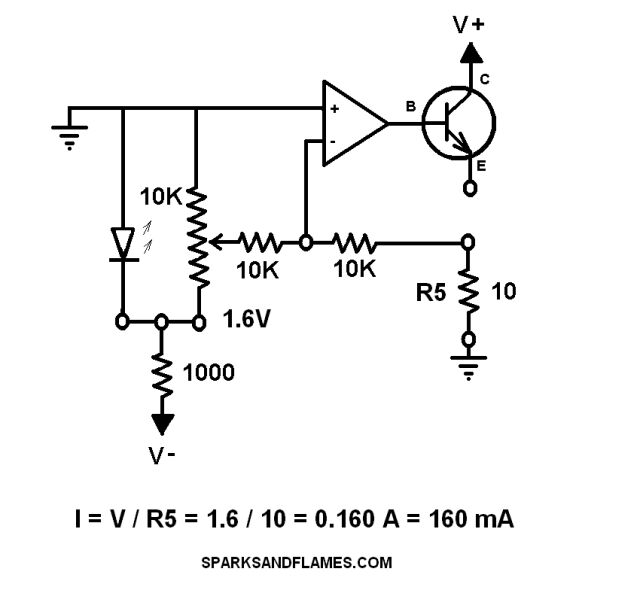
This circuit uses a potentiometer and an op-amp to make a 0 - 160 mA adjustable constant current source. A transistor is used to boost the output current of this circuit.
The current flowing through the transistor is limited only by the control signal from the op-amp.
R5 is not a current limiting resistor. R5 is a sense resistor.
R5 is far too small to limit current to protect the transistor.
Divide the voltage drop across R5 to get charging current.
Use 1 ohm or 10 ohms or 100 ohms for the value of R5. This makes for very easy calculation.
| VOM Reading | R5 | I Charging Current |
| 1 volt | 1 ohm | 1 amp |
| 1 volt | 10 ohm | 100 ma |
| 1 volt | 100 ohm | 10 ma |
I used a 2N2222A NPN transistor from Radio Shack. Any NPN transistor will work if it can handle the voltage, current and power.
Salvage a large high voltage transistor complete with large heat sink from a dead TV.
Use star grounding.
There are a lot of ways to destroy the transistor.
- Connecting the Emitter to ground.
- Connecting V+ to Base.
- Opamp control circuit applying V+ to the Base .

|

|
Charge Rate
Wall Warts
Simple 1 Resistor Battery Charger
Constant Current Battery Charger from 2 LED's and a NPN Transistor
9V Battery Charger from 2 NPN Transistors
Adjustable Charge Rate Battery Charger from Op Amp
0 - 160 mA Adjustable Charge Rate Battery Charger
Test Results
741C Cheat Sheet
sparksandflames.com
Sparks and Flames
Line2:
Fax:
Copyright © 2020